- New
![Extruder Gear Assembly for H2S [FAE033]](https://dev.marvle3d.co.nz/17351-large_default/extruder-gear-assembly-h2s-fae033-.jpg "Extruder Gear Assembly for H2S [FAE033]")
![Extruder Gear Assembly for H2S [FAE033]](https://dev.marvle3d.co.nz/17351-medium_default/extruder-gear-assembly-h2s-fae033-.jpg "Extruder Gear Assembly for H2S [FAE033]")
![Extruder Gear Assembly for H2S [FAE033]](https://dev.marvle3d.co.nz/17350-medium_default/extruder-gear-assembly-h2s-fae033-.jpg "Extruder Gear Assembly for H2S [FAE033]")
![Extruder Gear Assembly for H2S [FAE033]](https://dev.marvle3d.co.nz/17352-medium_default/extruder-gear-assembly-h2s-fae033-.jpg "Extruder Gear Assembly for H2S [FAE033]")

228 Bush Road, Rosedale | Mon–Sat 9:30–4:30

Auckland Local Stock
Authorized NZ Distributor – Marvle3D
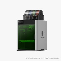
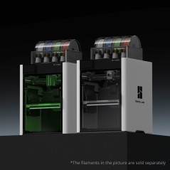
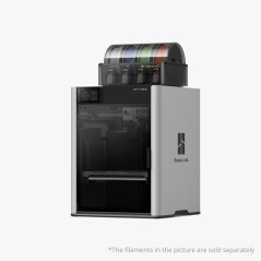
*Extruder Gear Assembly H2S [FAE033]
-Precision extruder gear assembly component
-Controls and advances filament movement
-Designed for smooth and consistent extrusion
-Supports reliable printing performance
-Facilitates easier filament loading and changes
Compatible With: Bambu Lab H2S
Why Marvle3D?
Marvle3D—New Zealand’s expert since 2016, offering friendly support, in-store demos, and one of the country’s largest ranges.
 Security policy(edit with the Customer Reassurance module)
 Delivery policy(edit with the Customer Reassurance module)
 Return policy(edit with the Customer Reassurance module)
Replace H2S Extruder Gear Assembly
Precautions:
Please be sure to follow the disassembly sequence outlined in this article strictly. Especially before removing the cover of the extruder, make sure to first remove the extruder filament sensor (handle with care to avoid pulling too hard), as failure to do so may result in the wiring of the sensor broken.
Disassembly Instructions
Step 1: Remove the Hotend
Refer to this tutorial:https://wiki.bambulab.com/zh/h2s/maintenance/replace-silicone-sock-and-hotend to remove the hotend.
Step 2: Disconnect the PTFE Tube
Press the pneumatic connector to disconnect the PTFE tube;
Step 3: Remove the Rotating Wheel
Rotate the rotating wheel and take it off.
Step 4: Loosen the Cutter Handle
Hold the cutter handle and use a screwdriver to remove 1 screw. After the screw is fully removed, gently release the cutter handle and let it hang naturally.
Step 5: Remove the Filament Sensor
Use an H2.0 Allen key to remove 2 screws. If possible, attach double-sided tape to the top of the toolhead to place the filament sensor, preventing it from falling during subsequent disassembly and assembly. Note: Do not pull hard when removing the filament sensor, and handle it carefully to avoid damaging the black FPC cable.
Step 6: Remove the Extruder Unit Front Cover
Use an H2.0 Allen key to loosen the tension driven lever locking screw on the side by one full turn;
Use an H2.0 Allen key to remove the 4 screws on the front cover.
Remove the extruder unit front cover.
Step 7: Remove the Driven Wheel Bracket
Use an H2.0 Allen key to remove the side screw. The internal spring and end cap may easily fall off when removing the bracket, so handle it carefully to prevent loss.
Step 8: Remove the Extruder Gear
Gently shake the large extruder gear and pull it out directly.
Assembly Instructions
Step 1: Install the Extruder Gear
Install the extruder gear.
Step 2: Install the Driven Wheel Bracket
Mount the driven wheel bracket onto the corresponding rotating shaft. Assemble the spring and end cap in the correct orientation and position (refer to the correct and incorrect examples below), place them in the corresponding position on the driven wheel bracket, and screw in the side screw to hold them in place—do not fully tighten yet.
IMPORTANT!
Ensure the spring and end cap are installed correctly; otherwise, the extruder may fail to grip the filament, leading to printing errors.
Left: Correct demonstration, with the screw pressing against the concave surface of the end cap;
Right: Incorrect demonstration, with the end cap in the wrong position, preventing the spring from being compressed.
Pre-lock the side screw by 2-3 turns—do not fully tighten, as this may hinder front cover installation.
Step 3: Install the extruder unit front cover
Reattach the extruder unit front cover and screw in the 4 front cover screws.
Tighten the extruder side screw;
Step 4: Install the filament sensor
When installing the extruder filament sensor, make sure the black FPC cable is not bent and is placed smoothly into the gap. Then fasten the extruder filament sensor with 2 screws.
Step 5: Reattach the Cutter Handle
Before re-tightening the screw, hold the cutter handle firmly in position. When tightening the screw, avoid excessive force to prevent thread stripping.
How to Verify Completion/Success
Turn the printer back on and control filament filamenting and retraction via the screen to confirm proper operation
Specific References
No customer reviews for the moment.
Auckland Local Stock
Authorized NZ Distributor – Marvle3D
*Extruder Gear Assembly H2S [FAE033]
-Precision extruder gear assembly component
-Controls and advances filament movement
-Designed for smooth and consistent extrusion
-Supports reliable printing performance
-Facilitates easier filament loading and changes
Compatible With: Bambu Lab H2S
Why Marvle3D?
Marvle3D—New Zealand’s expert since 2016, offering friendly support, in-store demos, and one of the country’s largest ranges.
![Bambu Lab Extruder Filament Sensor for H2S & H2S Laser Printer [FAC142]](https://dev.marvle3d.co.nz/16342-home_default/bambu-lab-part-extruder-filament-sensor-for-h2s.jpg)
![Bambu Lab Extruder Filament Sensor for H2S & H2S Laser Printer [FAC142]](https://dev.marvle3d.co.nz/16340-home_default/bambu-lab-part-extruder-filament-sensor-for-h2s.jpg)

![Cooling Fan for H2S [FAF020]](https://dev.marvle3d.co.nz/17347-home_default/cooling-fan-for-h2s-faf020-.jpg)
![Cooling Fan for H2S [FAF020]](https://dev.marvle3d.co.nz/17348-home_default/cooling-fan-for-h2s-faf020-.jpg)
![Heatbed Unit 220V Printer for H2S [FAC150]](https://dev.marvle3d.co.nz/16702-home_default/bambu-lab-part-filament-buffer-for-p2s.jpg)
![Heatbed Unit 220V Printer for H2S [FAC150]](https://dev.marvle3d.co.nz/16703-home_default/bambu-lab-part-filament-buffer-for-p2s.jpg)