- New
![Bambu Lab MC Board for P2S 3D Printer [DLB052]](https://dev.marvle3d.co.nz/17499-large_default/mc-board-for-p2s-dlb052-.jpg "Bambu Lab MC Board for P2S 3D Printer [DLB052]")
![Bambu Lab MC Board for P2S 3D Printer [DLB052]](https://dev.marvle3d.co.nz/17499-medium_default/mc-board-for-p2s-dlb052-.jpg "Bambu Lab MC Board for P2S 3D Printer [DLB052]")
![Bambu Lab MC Board for P2S 3D Printer [DLB052]](https://dev.marvle3d.co.nz/17500-medium_default/mc-board-for-p2s-dlb052-.jpg "Bambu Lab MC Board for P2S 3D Printer [DLB052]")

228 Bush Road, Rosedale | Mon–Sat 9:30–4:30

Auckland Local Stock
Authorized NZ Distributor – Marvle3D
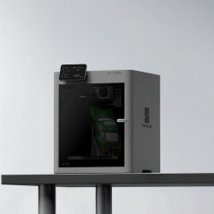
*MC Board for P2S [DLB052]
-Main control board for printer operation
-Integrated microprocessors and driver chips
-Controls motion and system functions
-Designed for stable and reliable performance
-Genuine replacement main control board
Compatible Printers: Bambu Lab P2S
Why Marvle3D?
Marvle3D—New Zealand’s expert since 2016, offering friendly support, in-store demos, and one of the country’s largest ranges.
 Security policy(edit with the Customer Reassurance module)
 Delivery policy(edit with the Customer Reassurance module)
 Return policy(edit with the Customer Reassurance module)
Remove the MC Then AC Board
Step 1: Remove Blocking Components
Please refer to the following wiki guidelines to remove the PTFE tube bracket, filament buffer, and rear panel.
PTFE Tube Bracket Replacement Guide https://wiki.bambulab.com/en/p2s/maintenance/replace-ptfe-tube-bracket
Filament Buffer Replacement Guide https://wiki.bambulab.com/en/p2s/maintenance/replace-filament-buffer
P2S Rear Panel Replacement Guide https://wiki.bambulab.com/en/p2s/maintenance/replace-rear-panel

Step 2: Remove the Purge Chute
Use the H1.5 Allen key to remove four screws (BT2x5) and remove the filament purge chute.
Step 3: Remove the MC Board Heat Sink
If the ultimate purpose is to replace the AC board, the side does not need to remove the fixed screws of the heat sink on the MC board.
Remove two heat sink fixing screws with H1.5 Allen key (red circle mark: M2x5);
Use an H2.0 Allen key to remove two heat sink fixing screws (green box marker: ST3x6).
Hold the heat sink from the printer by hand, pay attention to avoid the cable when removing the heat sink, and avoid the heat transfer silicon grease on the heat sink to the cable.
Step 4: Remove the MC board
Disconnect the cables from the MC board. A total of 11 cables need to be removed. It may be a good idea to label each cable with some tape and a number corresponding with the below image to make reconnecting easier in a later step.
Remove the three screws holding the MC board to the printer's frame with an H1.5 hex wrench and the MC board should only be still be attached by the AC connector.
Once the MC board is free from the printer, there should be enough room to disconnect the AC board connector from the MC Board.
Step 5: Remove the Power Cover
Disconnect the red, blue, and gray heatbed power cables from the AC board, pictured below.
Use the H1.5 Allen key to remove the five screws from the power protection cover.
Pull the power protection cover away from the printer, leaving it attached by the heatbed wiring.
Step 6: Remove the AC Board
Open the orange power cord cover from the left side so it hinges out of the way. Correct Wiring: Brown/Red: Live wire (L) Blue: Neutral wire (N) Yellow-Green: Ground (PE) Under correct wiring, the AC board controls the live wire.
If the live and neutral wires are connected incorrectly, the AC board will instead control the neutral wire, causing the hotbed’s live wire to remain constantly energized, which may result in increased leakage current. In extreme cases:
If the heated bed becomes deformed and the heating element is damaged, causing the live wire to come into contact with the aluminum bed plate, the live wire and ground wire may become connected. This can blow the fuse and damage the power supply circuitry. Loosen all three screws using a Phillips head screwdriver until each cable fork connector comes free. Make note of the order of the cables to replace them correctly later.
Specific References
No customer reviews for the moment.
Auckland Local Stock
Authorized NZ Distributor – Marvle3D
*MC Board for P2S [DLB052]
-Main control board for printer operation
-Integrated microprocessors and driver chips
-Controls motion and system functions
-Designed for stable and reliable performance
-Genuine replacement main control board
Compatible Printers: Bambu Lab P2S
Why Marvle3D?
Marvle3D—New Zealand’s expert since 2016, offering friendly support, in-store demos, and one of the country’s largest ranges.
![AC Board - HV for P2S [DLB054]](https://dev.marvle3d.co.nz/17372-home_default/ac-board-hv-for-p2s-dlb054-.jpg)
![AC Board - HV for P2S [DLB054]](https://dev.marvle3d.co.nz/17373-home_default/ac-board-hv-for-p2s-dlb054-.jpg)
![Bambu Lab AP Board - HV for P2S 3D Printer [DLB051]](https://dev.marvle3d.co.nz/17498-home_default/ap-board-hv-for-p2s-dlb051-.jpg)
![Bambu Lab AP Board Cover for P2S 3D Printer [DLB049-V2]](https://dev.marvle3d.co.nz/17496-home_default/ap-board-cover-for-p2s-dlb049-v2-.jpg)
![Bambu Lab AP Board Cover for P2S 3D Printer [DLB049-V2]](https://dev.marvle3d.co.nz/17497-home_default/ap-board-cover-for-p2s-dlb049-v2-.jpg)
![Bambu Lab Extruder Connection Board for P2S 3D Printer [DLB056]](https://dev.marvle3d.co.nz/17501-home_default/extruder-connection-board-for-p2s-dlb056-.jpg)
![Bambu Lab Extruder Connection Board for P2S 3D Printer [DLB056]](https://dev.marvle3d.co.nz/17502-home_default/extruder-connection-board-for-p2s-dlb056-.jpg)
![Eddy Sensor for P2S [FAC155]](https://dev.marvle3d.co.nz/16708-home_default/bambu-lab-part-filament-buffer-for-p2s.jpg)
![Eddy Sensor for P2S [FAC155]](https://dev.marvle3d.co.nz/16709-home_default/bambu-lab-part-filament-buffer-for-p2s.jpg)
![Extruder Gear Assembly for P2S [FAE035]](https://dev.marvle3d.co.nz/16745-home_default/bambu-lab-part-filament-buffer-for-p2s.jpg)
![Extruder Gear Assembly for P2S [FAE035]](https://dev.marvle3d.co.nz/16744-home_default/bambu-lab-part-filament-buffer-for-p2s.jpg)